Murphy’s and Ratje’s history of the waste incinerator, starts with late 19c and early 20c models. At the time, un-sorted domestic waste and animal corpses were burnt without any fume filtration, resulting in unpleasant smells, acid rain and illnesses to the nearby residents. Today, the energy from waste technology has become significantly more complex and sustainable. Today I visited two Suez Energy-from-Waste Plants near Middlesbrough, Lines 1, 2 and 3 at Tees Valley (STV) and the two lines at Wilton International. The notes and images below summarise the key stages of the process, which is similar on both sites, as well as in most other EfW facilities.
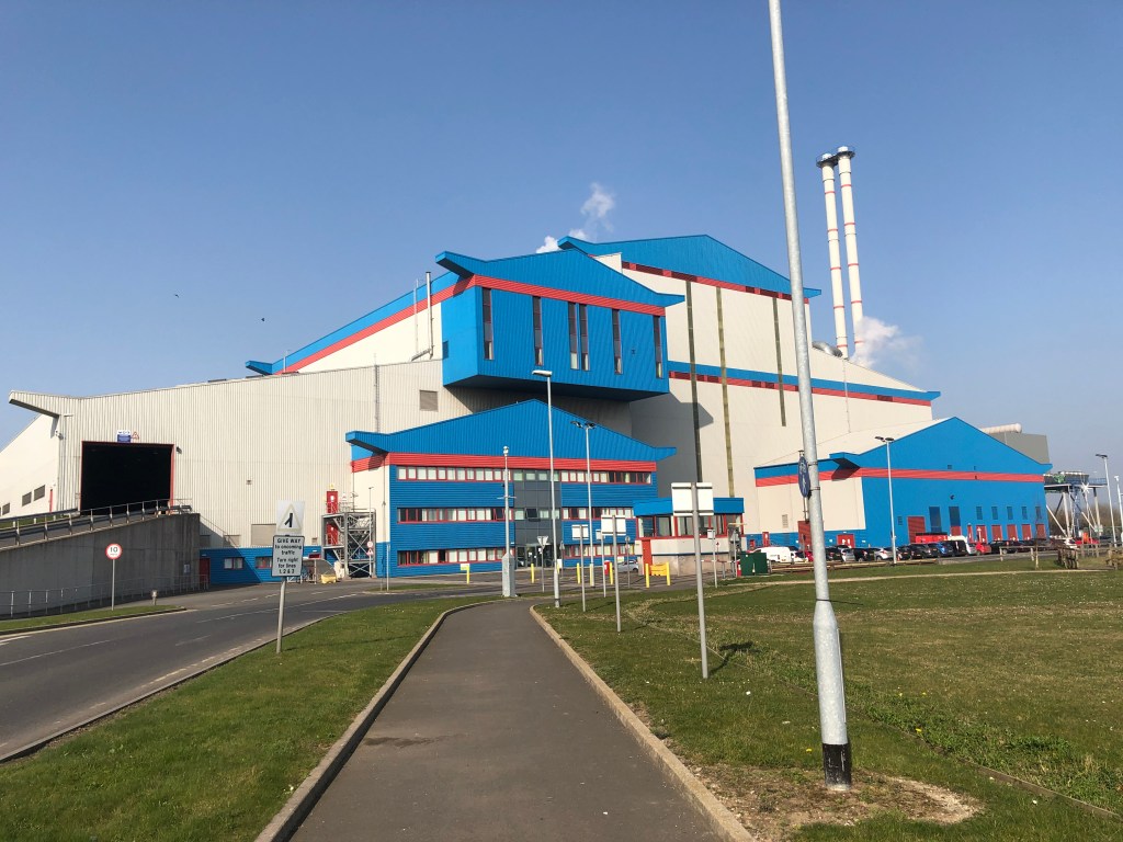
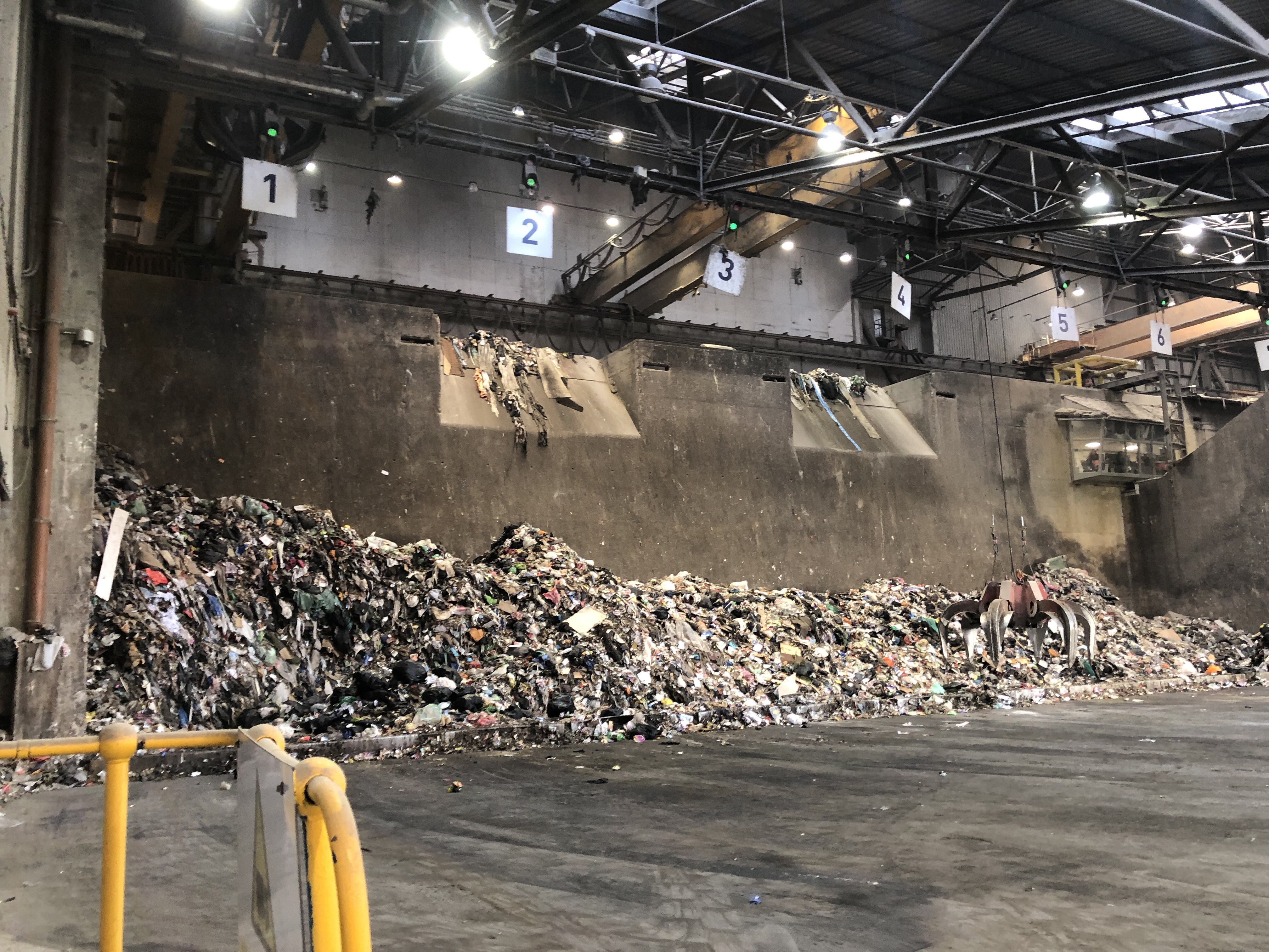
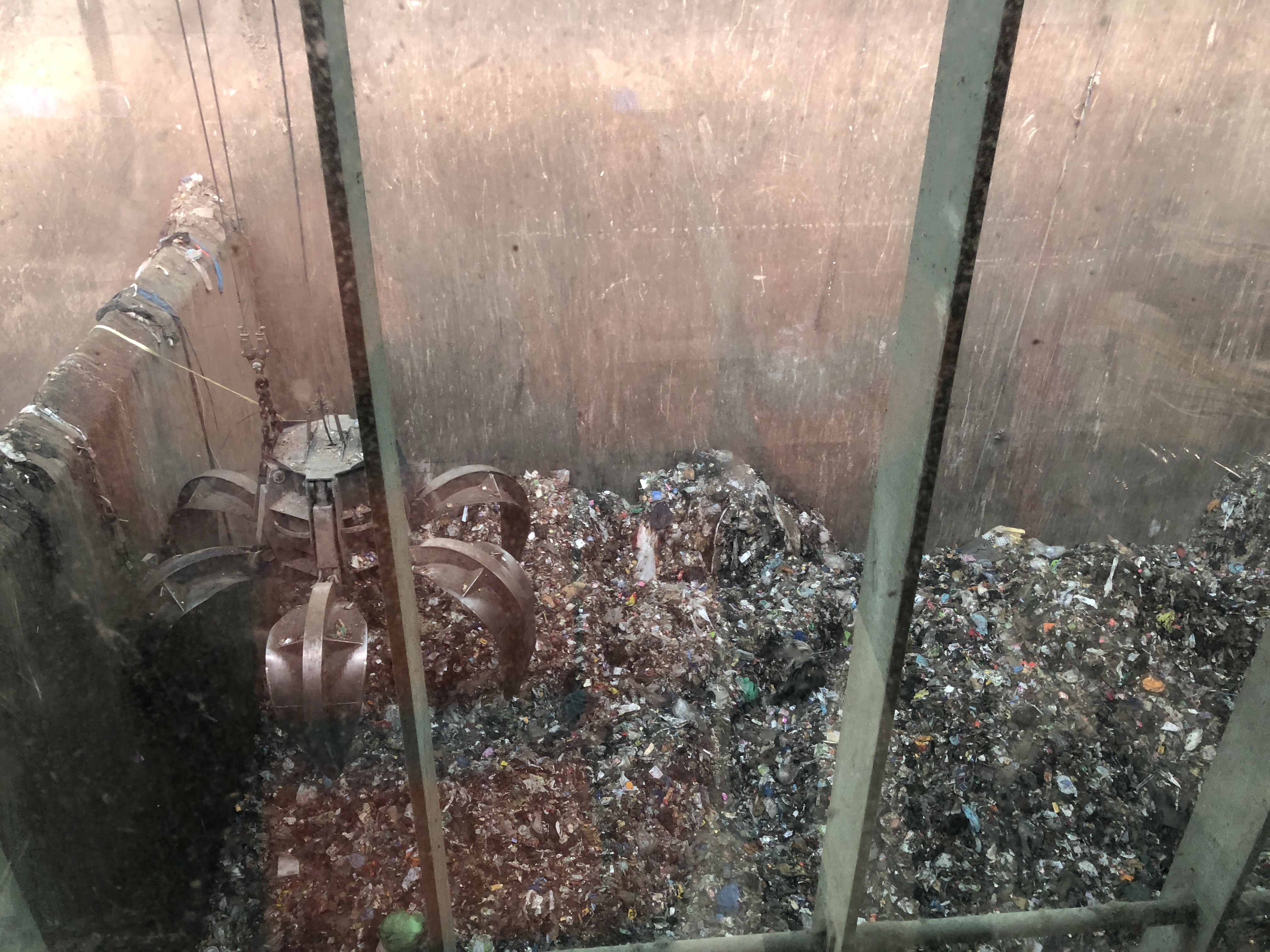
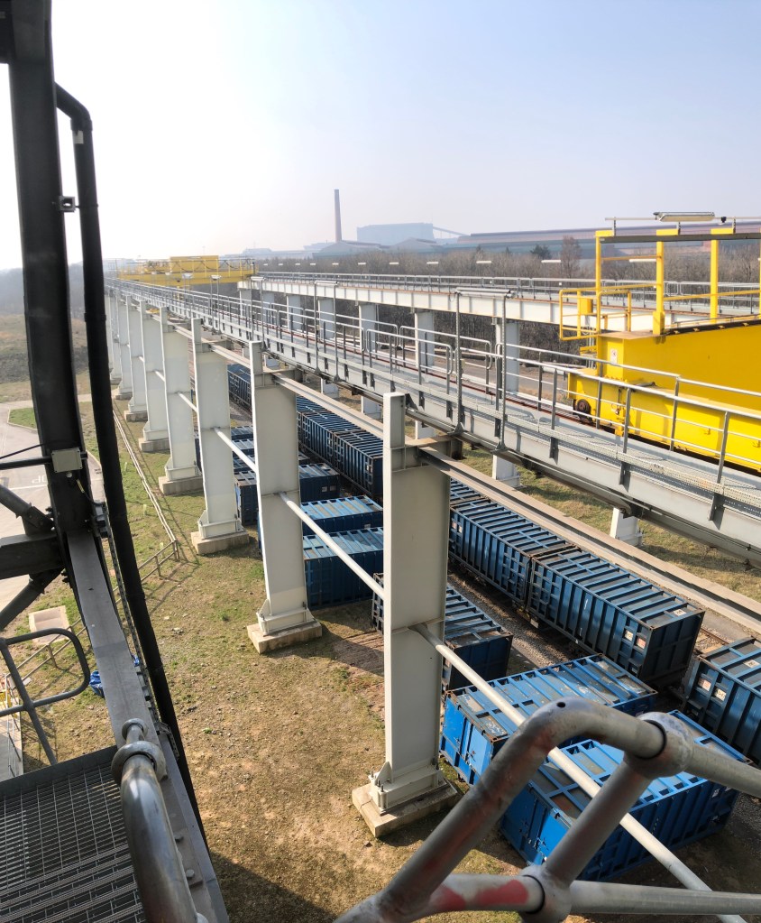
1 . The waste is brought into the large tipping hall. Trucks bring material to STV from Gateshead and Middlesbrough regions (some of it directly from households), whereas trains take it to Wilton from Merseyside (2000 tonnes a night). A grab loads approx. 1 t. the waste into the feeding chute. The staff member or an automated system operating the grab ensures there are no gaps between the chute edges the waste pile to prevent air and gases coming in and out of the system. Where waste does not undergo any pre-sorting prior to arriving, it creates a higher calorific value, i.e. produces more energy per tonne.

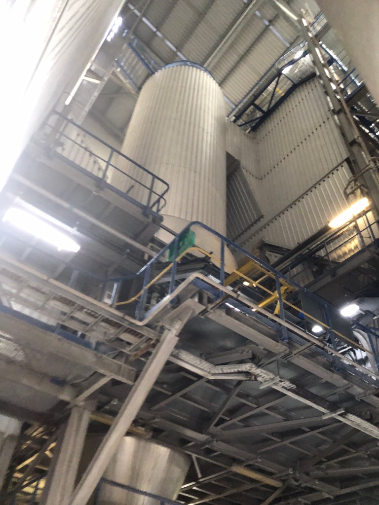
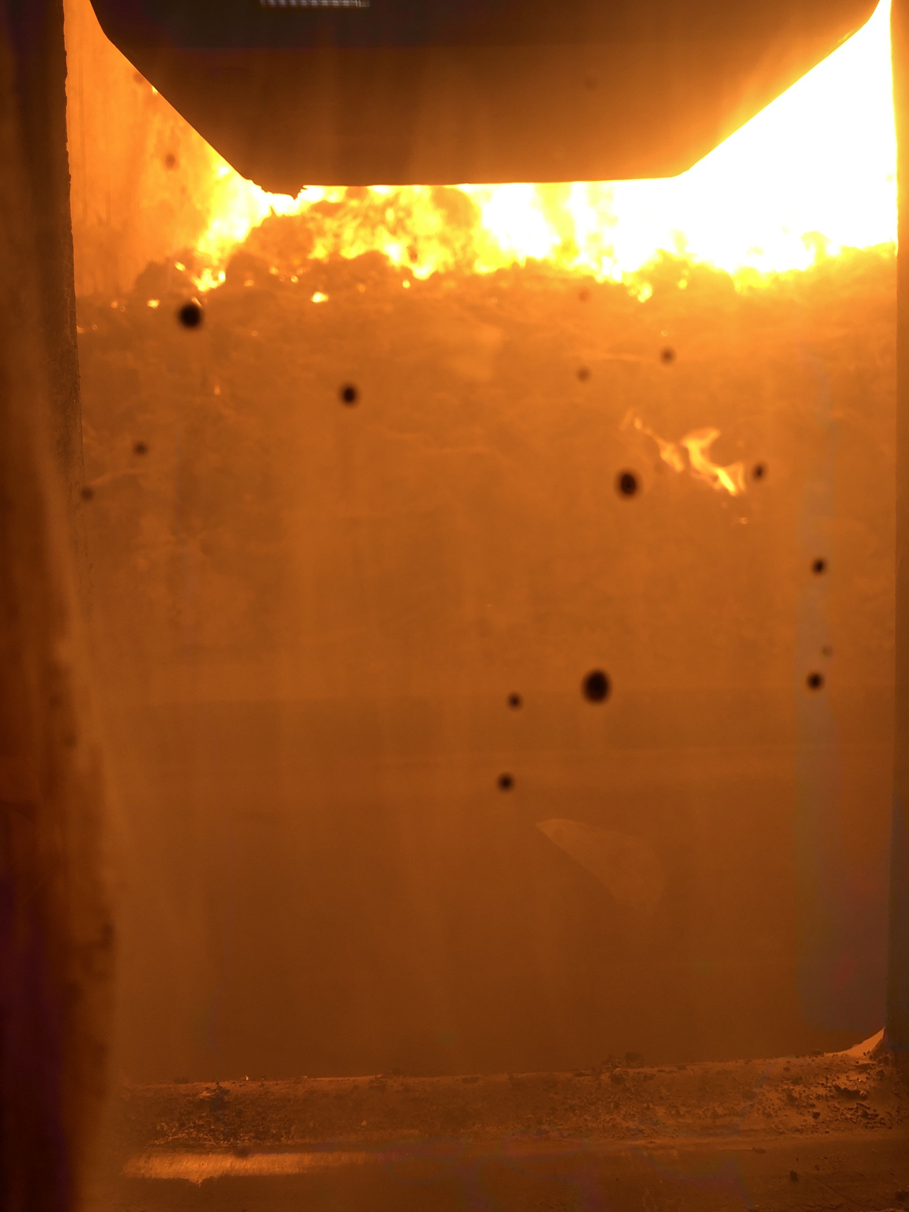
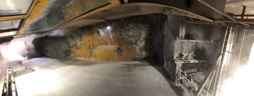
2 . Waste progresses along the incinerator grates, where most burning and heat occurs around the half way point. The line of the flame is well defined, unless there is an issue with the facility. Water pipes run throughout the incinerator walls. For a piece of waste it normally takes around 4 hours from being added onto the grates to coming from the other side in the form of ash.

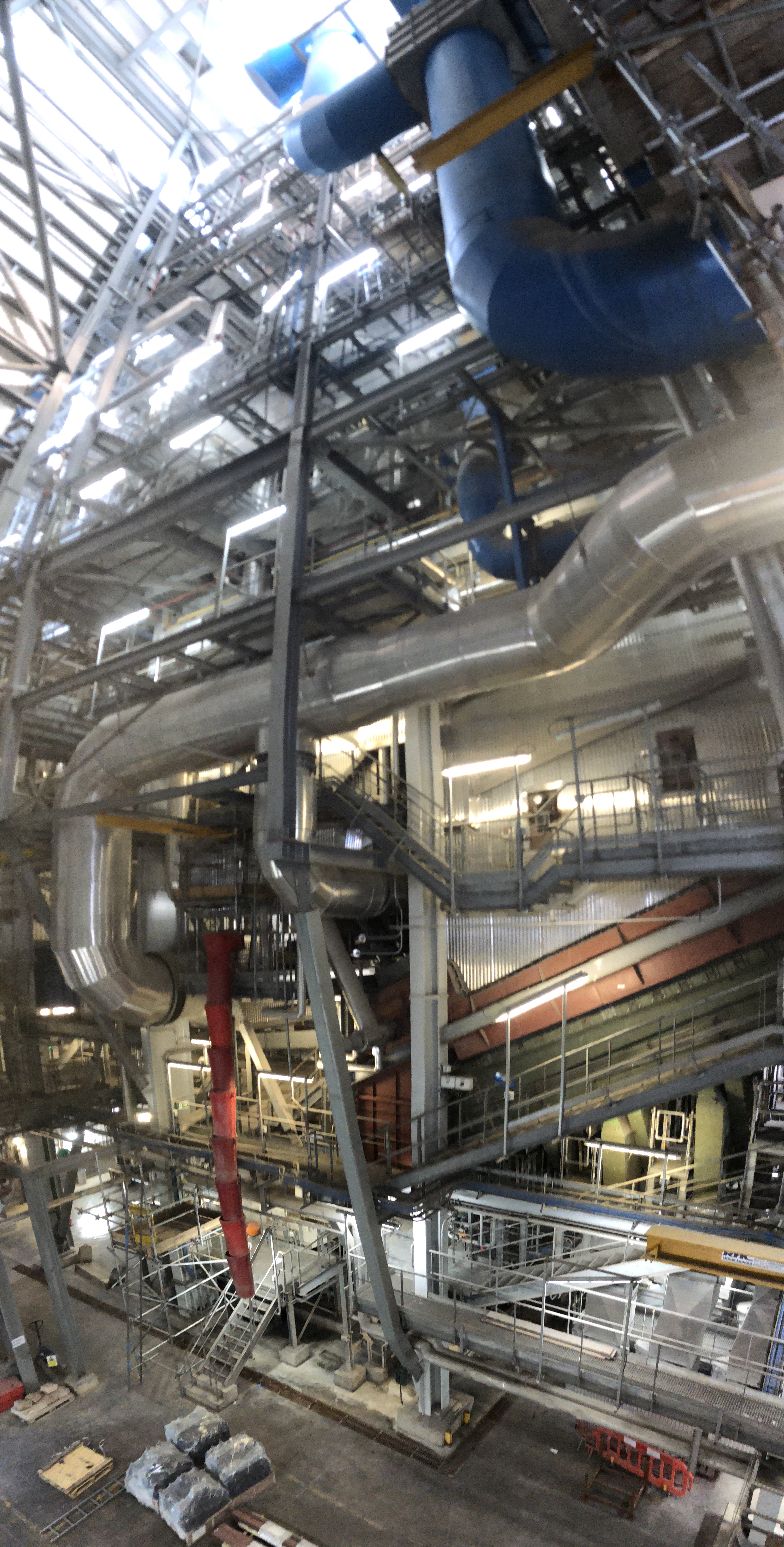
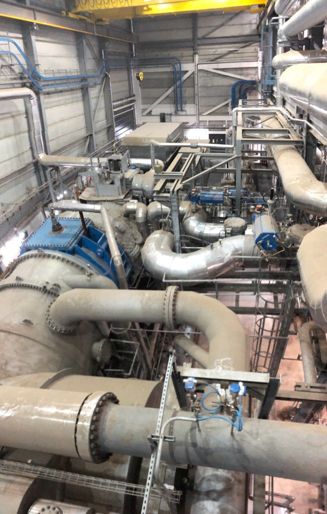
3 . The water in the pipes gradually reaches a very high temperature (up to 500 C) and becomes super-heated steam, which is subsequently driven into a steam turbine . The turbine is connected to a generator which produces electricity. At Wilton the steam pipe running into the turbine is 8 inch and the turbine widens to a 2-3 m diameter (judging by appearance).
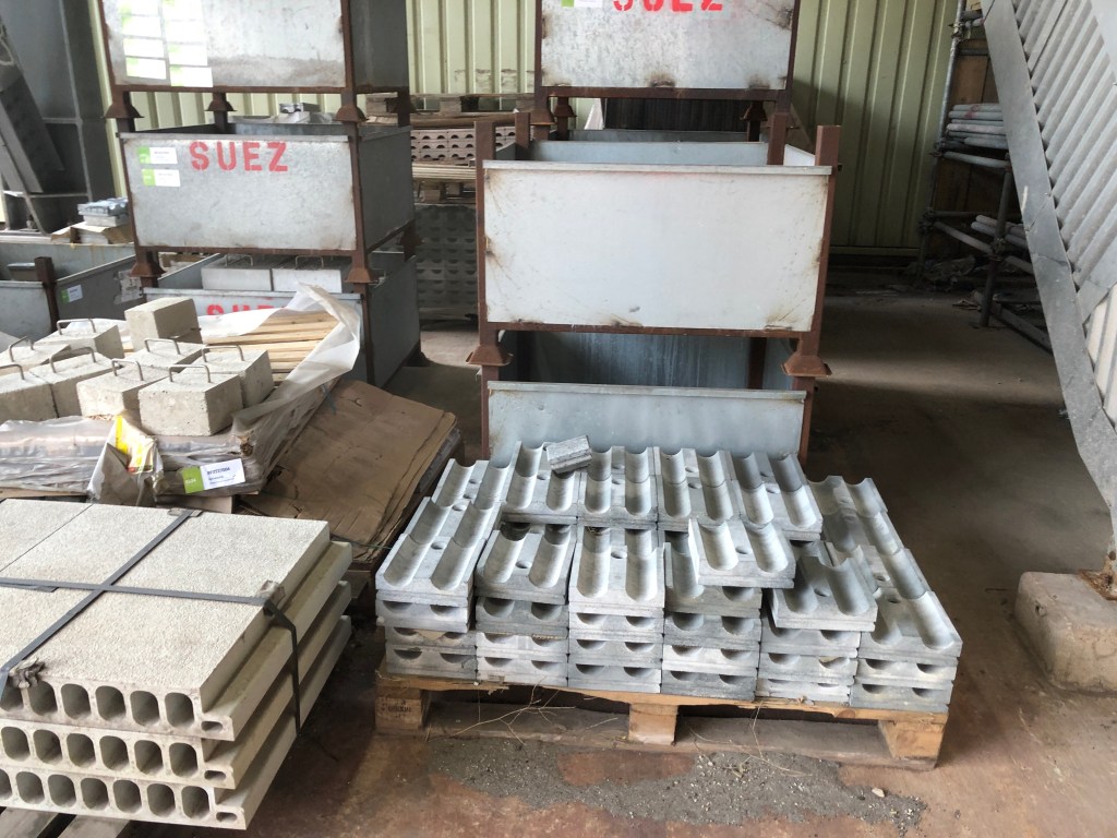
4 . After the lowest stage of the grate, the waste ashes are cooled down with water. The bottom ash is taken to a processing facility, where it is used to make aggregate. At Lines 1,2 and 3, the bottom ash is transported in trucks and at Wilton it is taken on a conveyor belt.
5 . At Lines 1,2 and 3 the water system is a closed loop. Once the steam passes through the turbine it is cooled using water from the river Tees and subsequently re-circulated to be re-heated through the incineration process. Given the small leaks within the system, some of the water is re-supplied into the loop from the ‘town’s’ water main (i. e. regular water supply).
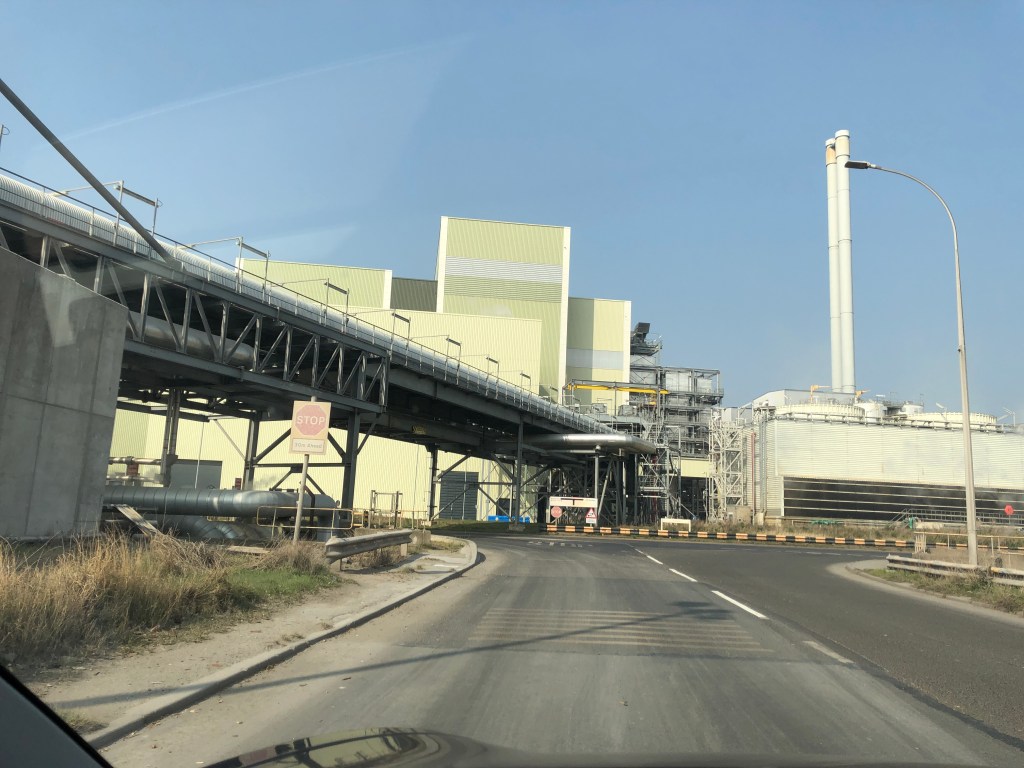
At Wilton, the turbine has a valve permitting some of the steam to be redirected away from the turbine and supplied to other industrial facilities at Wilton International. According to the EfW plant’s staff, the steam travels further than 3 km, given all the turnings of the pipes. District heating systems work in similar ways. Given the water leaving the EfW plant, new water is constantly being supplied, making Wilton’s system an ‘open system’.
6 . The fumes emerging from the burning process are filtered and purified. At Lines 1,2 and 3 this process is enclosed and takes as much of the plant’s space / volume as the incineration part. Lime and carbon particles are injected into the fume to attract and remove the acid elements. Subsequently, the fume is passed through bag filters for particle removal and then taken out of the plant via the chimney stack.